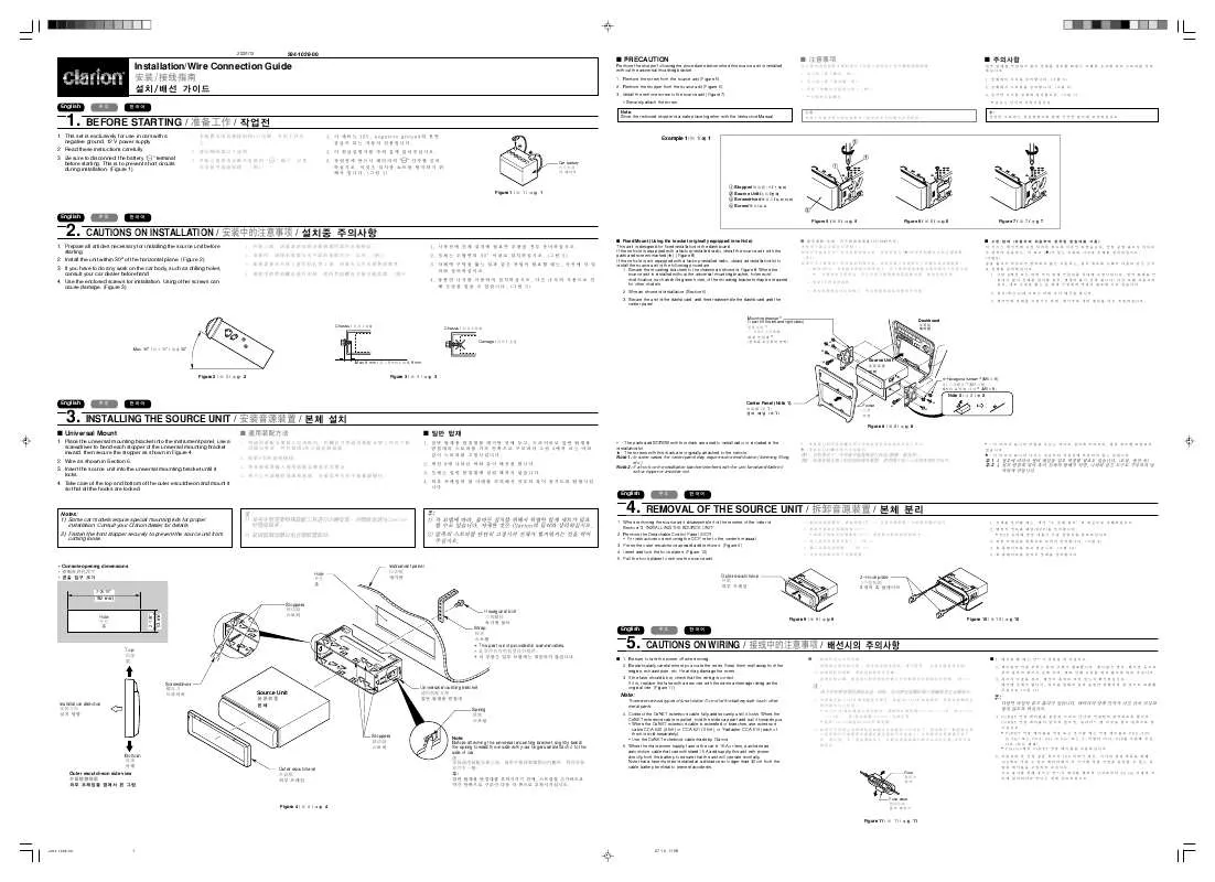
ユーザーズガイド CLARION DXZ576USB INSTALLATION GUIDE
Lastmanualsはユーザー主導型のハードウエア及びソフトウエアのマニュアル(ユーザーガイド・マニュアル・クイックスタート・技術情報など)を共有・保存・検索サービスを提供します。 製品を購入する前に必ずユーザーガイドを読みましょう!!!
もしこの書類があなたがお探しの取扱説明書・マニュアル・機能説明・回路図の場合は、今すぐダウンロード。Lastmanualsでは手軽に早くCLARION DXZ576USBのユーザマニュアルを入手できます。 CLARION DXZ576USBのユーザーガイドがあなたのお役に立てばと思っています。
CLARION DXZ576USBのユーザーガイドをLastmanualsがお手伝いします。


マニュアル抽象的: マニュアル CLARION DXZ576USBINSTALLATION GUIDE
詳しい操作方法はユーザーガイドに記載されています。
[. . . ] If the vehicle is equipped with a factory-installed radio, install the source unit with the parts and screws marked (★). (Figure 8) If the vehicle is not equipped with a factory-installed radio, obtain an installation kit to install the source unit in the following procedure. Secure the mounting brackets to the chassis as shown in Figure 8. When the source unit is installed without the universal mounting bracket, holes exist; modification, such as drilling new holes, of the mounting brackets may be required for other models. [. . . ] Secure the unit in the dashboard, and then reassemble the dashboard and the center panel.
Mounting bracket * (1 pair for the left and right sides)
Dashboard
Max. 8 mm / 8 mm / 8 mm
* *
★ ★
Figure 2 /
2/
2
Figure 3 /
3/
3
★
Source Unit
English
3. INSTALLING THE SOURCE UNIT /
■ Universal Mount
1. Place the universal mounting bracket into the instrument panel, use a screwdriver to bend each stopper of the universal mounting bracket inward, then secure the stopper as shown in Figure 4. Insert the source unit into the universal mounting bracket until it locks. Take care of the top and bottom of the outer escutcheon and mount it so that all the hooks are locked.
4–Hexagonal screw * (M5 × 8) 4 * (M5 × 8) * M5 × 8 4
/
■
1. 6
Note 2 / Center Panel (Note 1) 1 1
★
2/
2
Pocket
★ ★
■
1. 4
Figure 8 /
8/
8
∗ : The parts and SCREW with this mark are used to install radio or included in the installation kit. ★ : The screws with this mark are originally attached to the vehicle. Note 1: In some cases, the center panel may require some modification (trimming, filling, etc. ). Note 2: If a hook on the installation bracket interferes with the unit, bend and flatten it with a nipper or a similar tool.
∗ ★
∗
1 2
★
1 2
Notes: 1) Some car models require special mounting kits for proper installation. ∗ Use the CeNET extension cable made by Clarion. When the main power supply fuse in the car is 15 A or less, purchase an automotive cable that can withstand 15 A and supply this unit with power directly from the battery to ensure that the unit will operate normally. Note that a fuse must be installed at a distance no longer than 30 cm from the cable battery terminal to prevent accidents.
CCA-520 CCA-521 0. 6m CeNET 15A 30 cm 15A Y CCA-519
5.
Fuse case
Figure 4 /
4/
4 Figure 11 / 11 / 11
English
English
6. WIRE CONNECTIONS /
/
3 1 2
To external amplifier * To eliminate audio short circuits, do not remove the caps of unused RCA cables. CAUTION: Please make sure when connecting external power amplifier, that you properly, to the car chassis, ground the amplifier. If this is not done, severe damage to the source unit may happen.
7. SYSTEM EXAMPLE /
/
■ Example of iPod BB and Bluetooth BB connection ■ ■
iPod connector cable / /
■ Example of the system using an external amplifier (Audio Visual) ■ ■
0
1
*
!
6
iPod/ iPod mini
EA-1276
Antenna
*
2
1 6
CeNET input CeNET CeNET
# @ 3 $ 7
( &
or /
/
* This system has an external input jack on the front panel, so you can listen to your telephone calls or music from external devices on your car speaker.
4 5
Amp
Amp
%
16-Pin Connector Extension Lead (attached to the source unit) 16 16 +Gray / + Front Right -Gray/Black / //+
¥
8
9
Note: Use a CeNET extension cable that is less than 20 m in length. (including the Y-adapter CCA-519. ) 20 m CeNET CCA-519 CCA-519
Brown wire (Phone mute lead)★ ★ ★
20 m
CeNET
+White / + Front Left
/+ Connect to cellular phone mute lead.
∗ This source unit can control a total of 2 changers except 2 DVD changers exist in the system. ∗ 2 DVD 2 ∗ 2 DVD 2
-White/Black / -
/Yellow wire (Memory back-up lead)
+Purple / + Rear Right
/+
English
Connect directly to battery. -Purple/Black / /Fuse (15A) 15A 15A
+Green / + Rear Left
/+
Note: Some units do not have connecting leads or jacks. (Refer to ★. )
★ ★
-Green/Black / -
/-
Yellow wire (Bus power lead)★ ★ ★
Connect directly to battery.
4-Speaker system 4 4
Fuse (3A) 3A 3A Red wire (Power lead)
or
Accessory+12 V +12 V +12 V Blue/White wire (Amplifier turn-on lead)
English
No. [. . . ] 1 2 3 Description REAR RIGHT Black (Red) REAR LEFT Black (White) OEM STEERING WHEEL REMOTE CONTROL INPUT (Black)
2-Speaker system 2 2 Connect to remote turn-on lead of amplifier. +Gray / + Right Black wire (Ground lead) -Gray/Black / /) /+
1 2 3 4 5 6 7 8 9 0 !@ # $ % ¥ & * (
Source unit CeNET extension cable Y-adapter (sold separately) CD changer DVD changer RCA extension cable (sold separately) 4-Channel power amplifier Front speakers Rear speakers Monitor TV tuner module 5. 1ch surround decoder 5. 1ch surround decoder control unit Optical connector cable Center speaker (with amplifier) Subwoofer (with amplifier) External unit Aux Bluetooth BB (BLT370) Stereo mini-plug cable (sold separately)
1 2 3 4 5 6 7 8 9 0 !@ # $ % ¥ & * (
CeNET Y CD DVD RCA 4
TV 5. 1 5. 1
1 2 3 4 5 6 7 8 9 0 ! [. . . ]
CLARION DXZ576USBダウンロード上のご注意
Lastmanualsはユーザー主導型のハードウエア及びソフトウエアのマニュアル(ユーザーガイド・マニュアル・クイックスタート・技術情報など)を共有・保存・検索サービスを提供します。
お探しの書類がなかったり、不完全だったり、言語が違ったり、モデル名や言語が説明と違う場合など、いかなる場合でもLastmanualsはその責を負いません。またLastmanualsは翻訳のサービスもしていません。
規約に同意して「マニュアルをダウンロード」をクリックすればCLARION DXZ576USBのマニュアルのダウンロードが開始されます。
